Clachan Power Station - The power station: interior
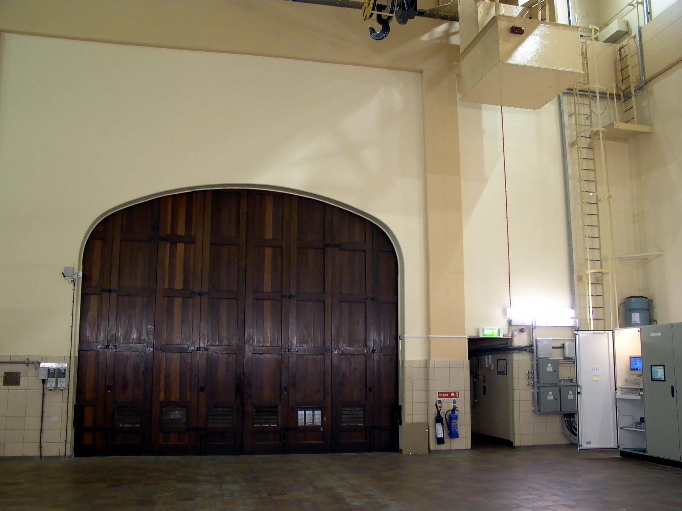
Passing through the personnel door mentioned in the description of the
station entrance brings you down a short passageway directly into the spacious
machine hall:
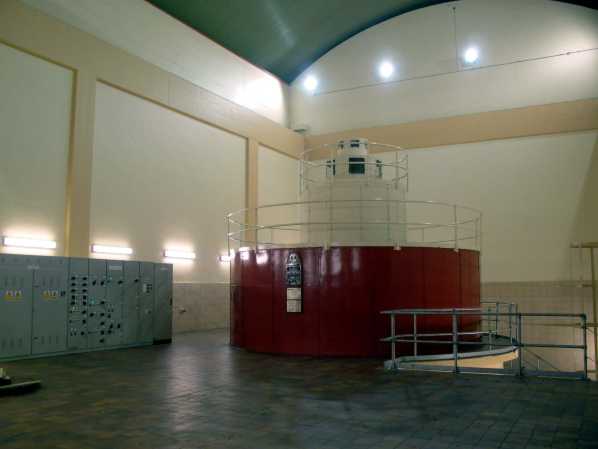
Photo: Clachan power station - control room
Photo by: Mike Ross
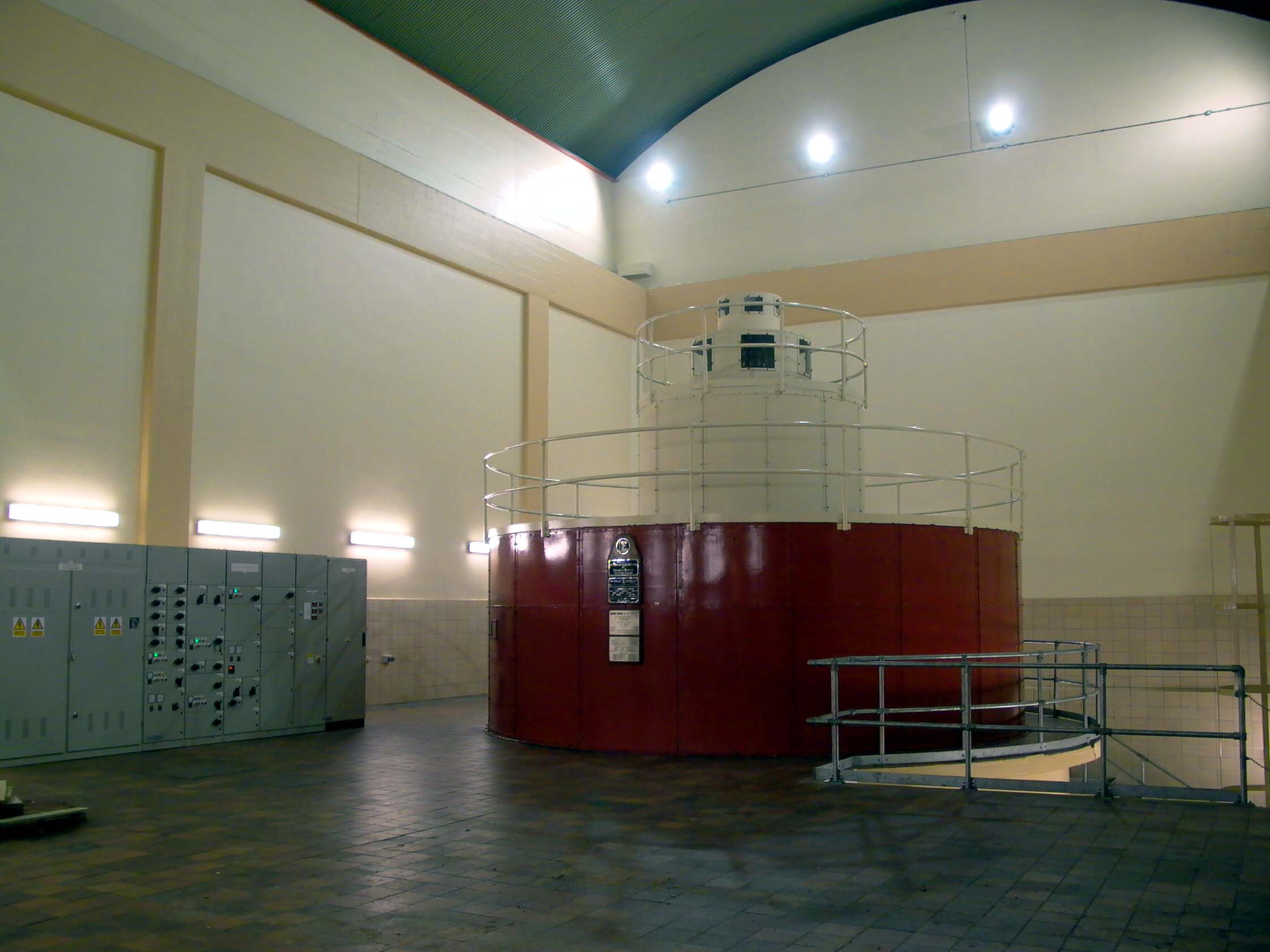
Looking back, we can see the main door of the station, and the passageway
we entered by. This station was refurbished in 2000, the cabinets of the
modern computer remote control & monitoring system can be seen near the wall:

Photo:Clachan power station - machine hall
Photo by: Mike Ross
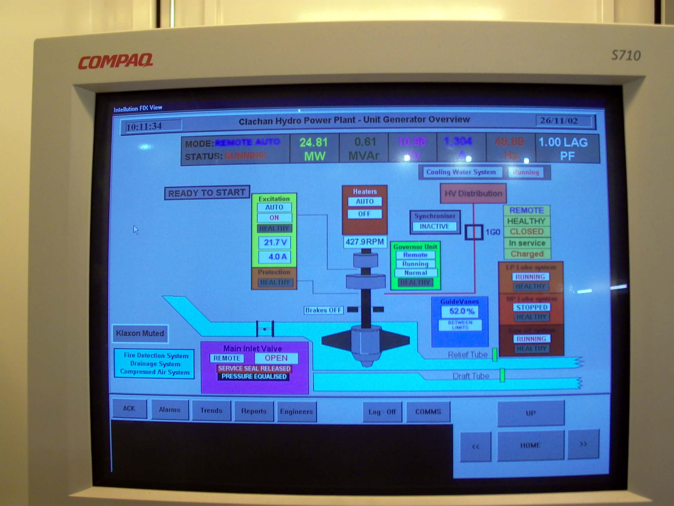
The computer seem looks fairly user-friendly, not sure what OS it's running...
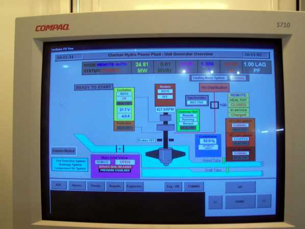
Photo: Clachan power station - computer control
Photo by: Mike Ross
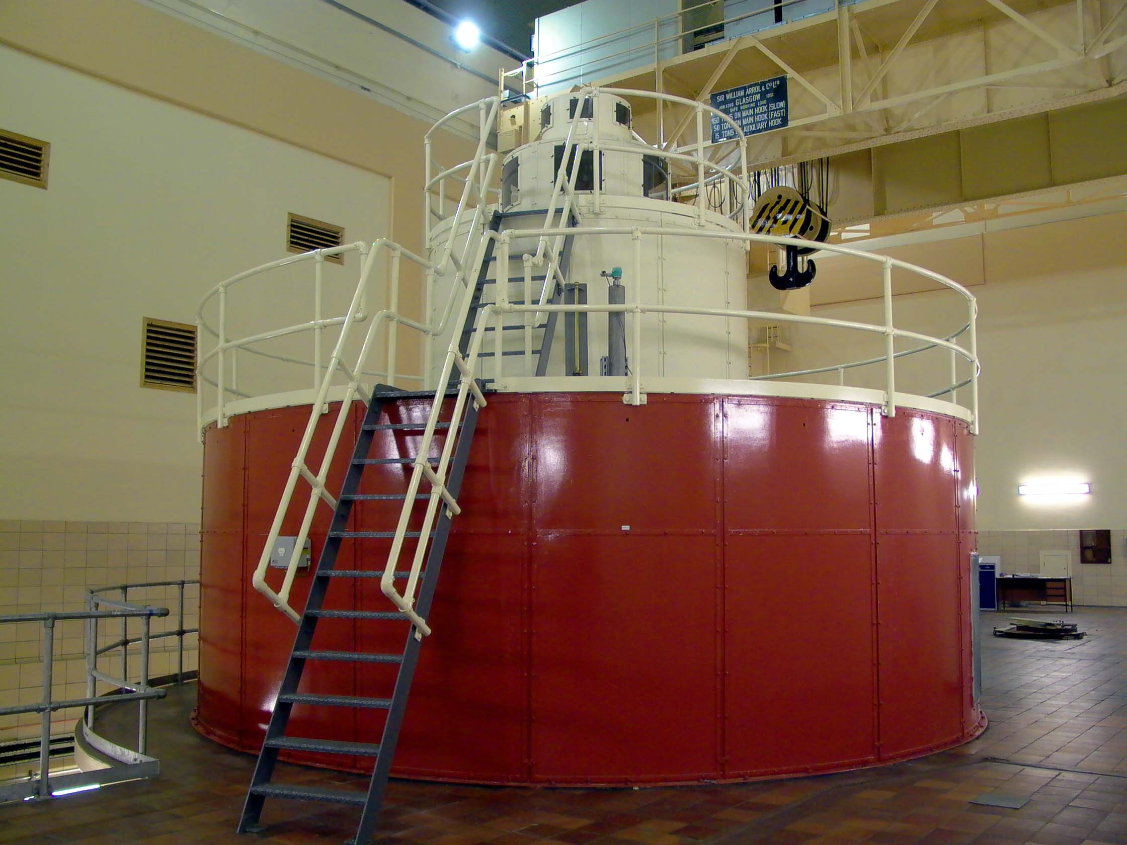
The generator. 40MW, built by English Electric. The most powerful single
generator in any UK hydro scheme (the dual-purpose motor/generators at
the major pumped storage schemes are of course much more powerful). Why
a large single generator when many stations with less total power have
two small generators?
First, Clachan doesn't have a compensation requirement - when it doesn't
run, no water flows, and none is required.
Second, traditionally Francis turbines have had the design characteristic of *relatively* poor part-load performance; they had been most efficient when running close to their design output. For this reason, it was frequently more economical in the long term to install two machines, so that when only half the station output was required,. it could be provided by running one of the two machines efficiently at full load, rather than a single big machine at half load. By the time Clachan was built, advances in Francis turbines design had somewhat negated this argument.
Third, Clachan was always intended to be a low load-factor station, running
at about 20% load factor - i.e. it was only in operation for perhaps 4-5
hours a day, to meet peak load. It spent most of its time either 'off'
or 'on', not somewhere in between.
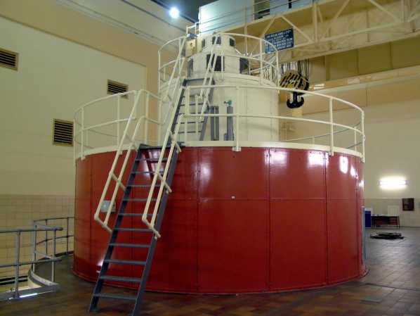
Photo: Clachan power station - generator
Photo by: Mike Ross
Looking down the stairs to the turbine floor. Generator to the right. The
large blue object just glimpsed through the grille in the floor is the
relief valve - designed to prevent a damaging pressure buildup in the spiral
casing if the load suddenly comes off the machine, by discharging water
into the tailrace, which is free-fowing.
The large gated-off opening in the wall next to the electrical switchgear
is an air pressure relief door. The door itself, blue in colour, can just
be made out. When the machine is started or stopped, a considerable 'bow
wave' of water can pass down the tail race tunnel. This can develop a partial
vacum in the tailrace, the air pressure door then opens against spring
pressure to allow air into the tailrace.
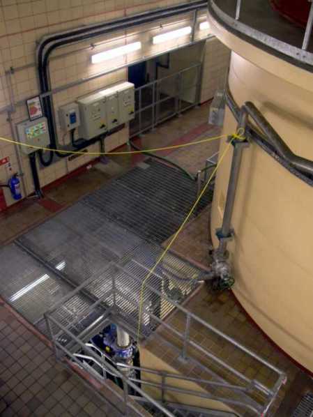
Photo: Clachan power station - turbine floor
Photo by: Mike Ross
On the turbine floor, looking down the access passage under the generator
support, to the turbine and shaft:
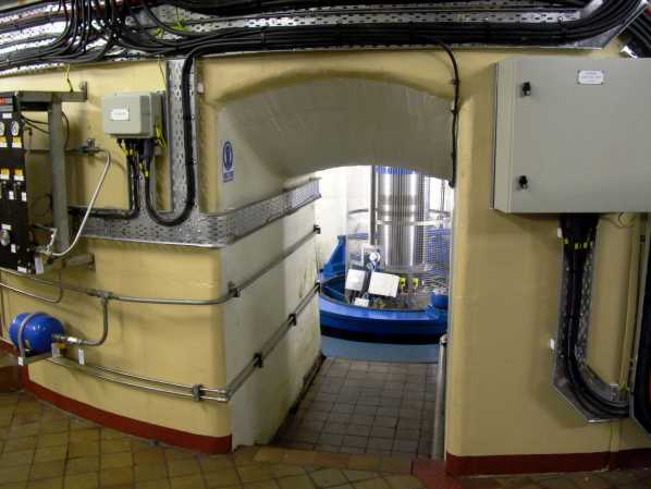
Photo: Clachan power station - turbine
Photo by: Mike Ross
Home Page
Last updated 5th March 2003
Style © 1998-2001 Subterranea Britannica
Words and images © 2003 Michael J. Ross

|