Culligran Power Station - High-Pressure System
The high-pressure system at Culligran (as illustrated in the drawing below)
comprises a 90 degree bend immediately following the control gate where
the LP tunnel passes below the surge chamber, a vertical shaft, a flat
heel, and a short length of high-pressure tunnel followed by a bifurcation,
with a large inlet penstock to the main turbine, and a much smaller penstock
to the compensation set. Obviously this whole area is normally full of
water, so I've had to draw on the NOSHEB archives to illustrate it.
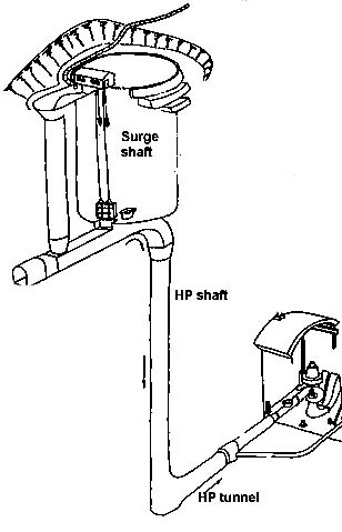
Drawing: Culligran high-pressure system
Drawing by: from photograph of NOSHEB drawing by Mike Ross
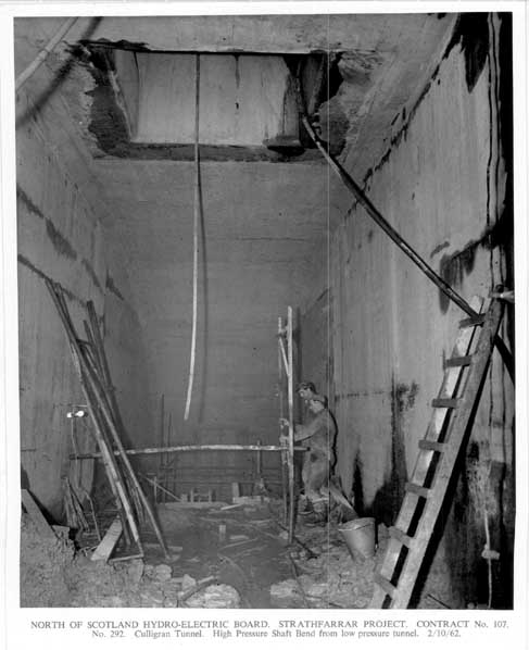
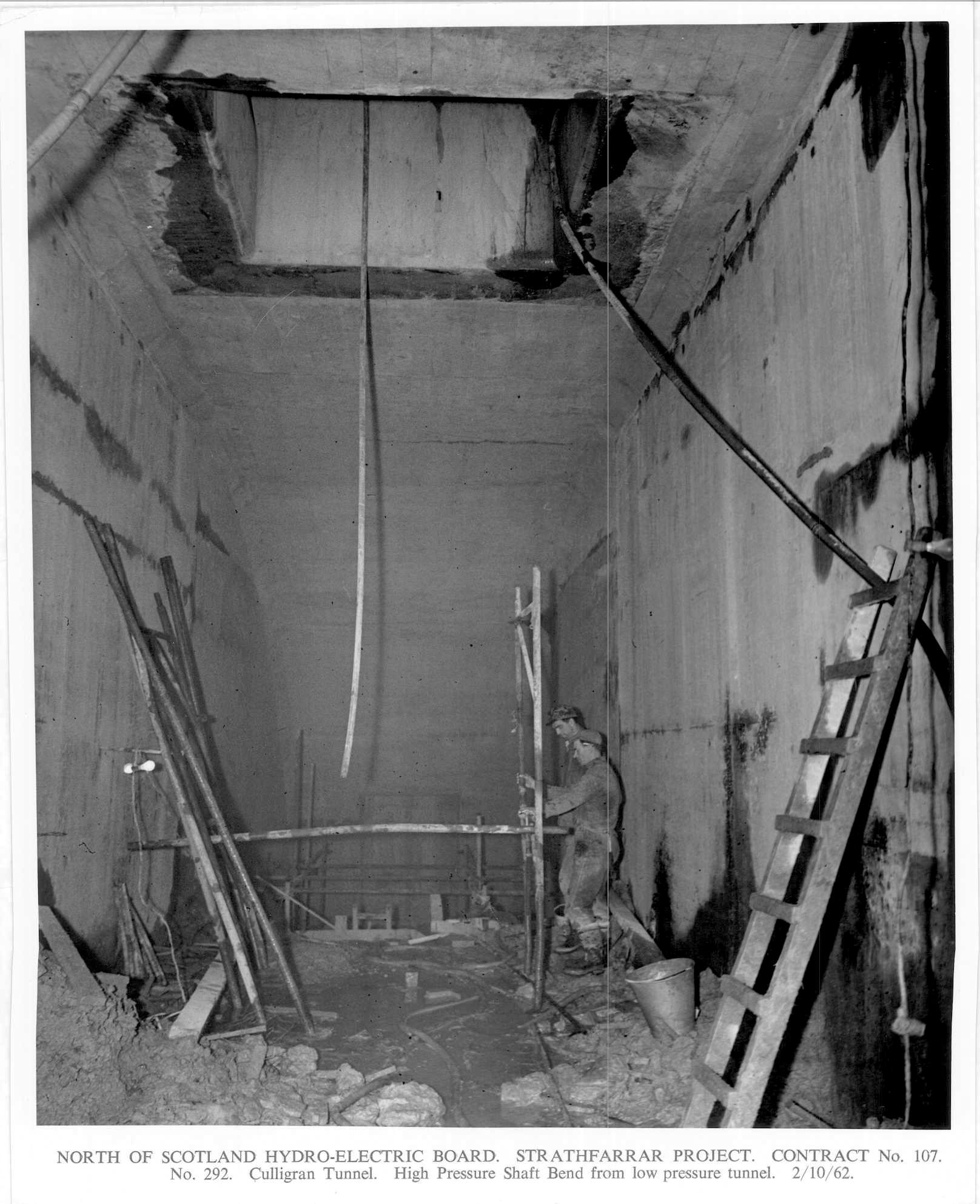
Photo: Culligran high-pressure system. Under the floor of the surge chamber,
the HP system starts with the bend where the horizontal LP tunnel transitions
into the vertical HP shaft. Above the bend is a square hole into the roof,
through to the floor of the surge chamber - to facilitate construction
access, lowering of materials etc.
Photo by: NOSHEB archives.
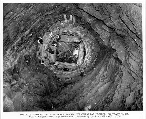
Photo: Culligran high-pressure system. Taken at a much earlier stage in
construction, looking down the high-pressure shaft from the floor of the
surge chamber. The task of lining the shaft with concrete has just started.
Photo by: NOSHEB archives.

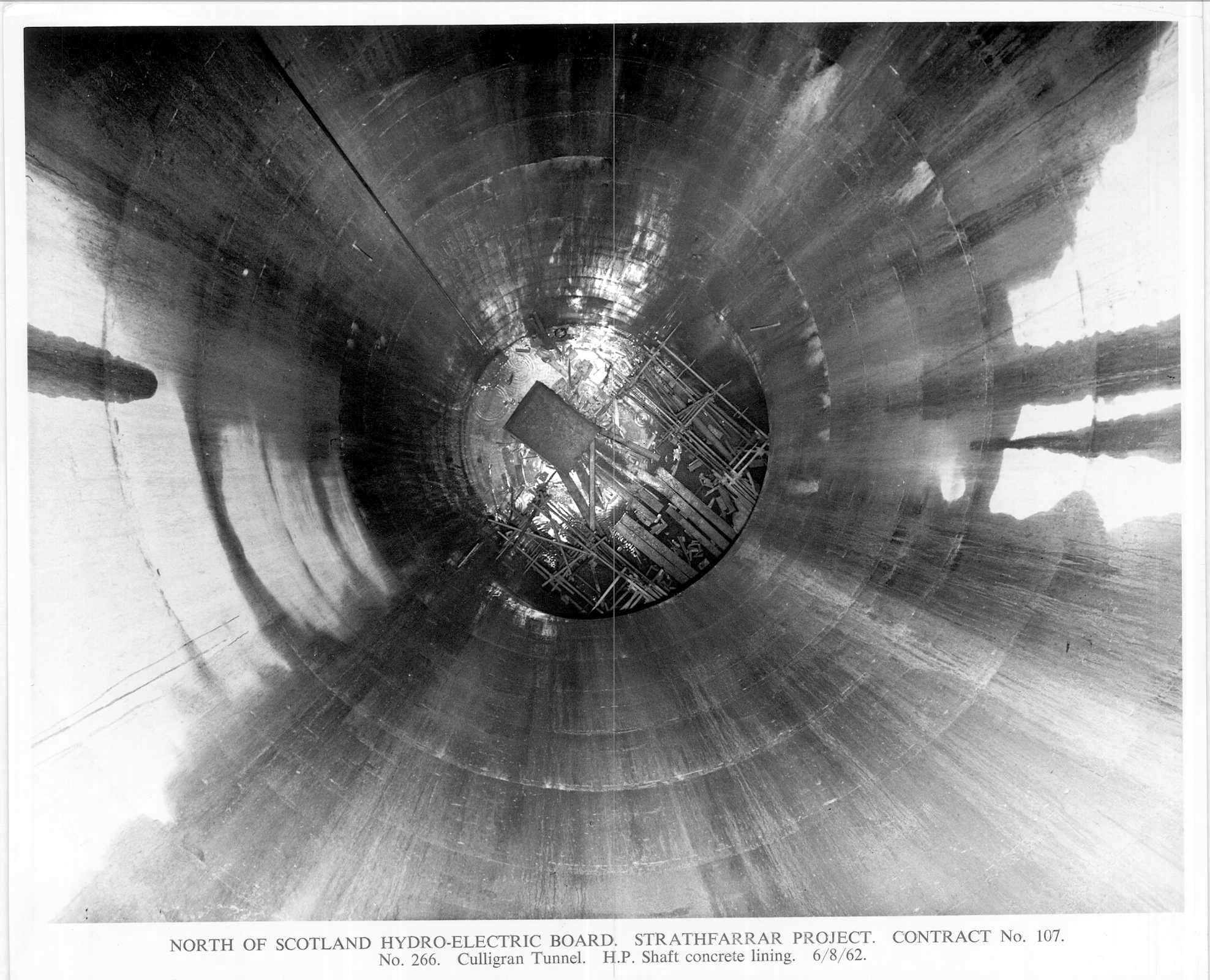
Photo: Same view as previous image, with concrete lining complete. HP tunnel
leads off to bottom right of shaft
Photo by: NOSHEB archives.
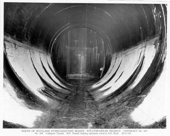
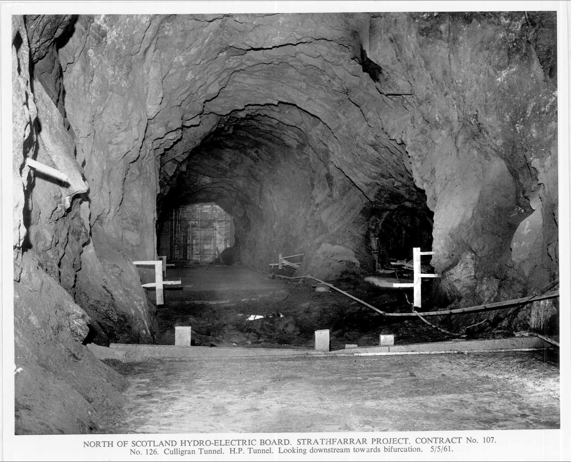
Photo: Culligran high-pressure system. The HP tunnel, looking upstream
to the base of the HP shaft..
Photo by: NOSHEB archives.
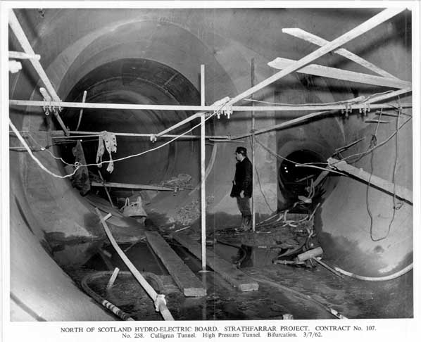
Photo: Culligran high-pressure system. From the same viewpoint as the previous
image, but turned 180 degrees - looking downstream to the HP tunnel bifurcation.
Main tunnel carries straight on the short distance to the main turbine
MIV; the branch on the right runs to the compensation set MIV.
Photo by: NOSHEB archives.

The same location as above, at a much earlier stage of construction - before
serious concreting had started. If you look carefully you can see the cavern
of the machine hall beyond the end of the left-hand tunnel.
Photo by: NOSHEB archives.
Home Page
Last updated 13th November 2005
Style © 1998-2001 Subterranea Britannica
Words and images © 2005 Michael J. Ross.
|