Culligran Power Station - Refurbishment When I visited the station in 2004, it was under refurbishment - the interior was mostly stripped, and the main 22MW set was in pieces. Only the compensation set was running - they refurbed that after the main set was completed and running again. 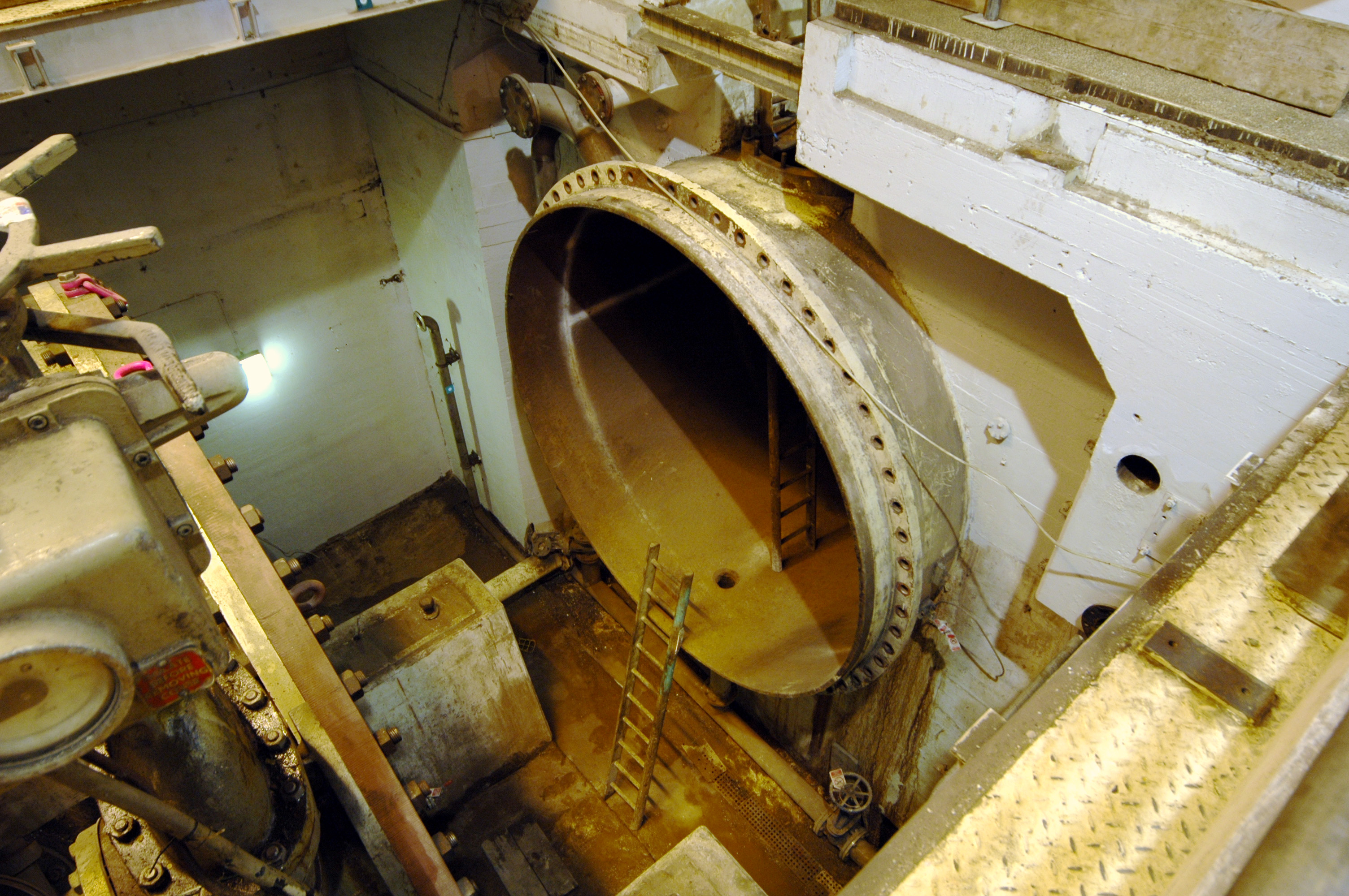 For starters, the MIV on the 22MW set was out. This pic was taken from the back wall of the station, looking towards the start of the spiral casing (where the ladders are). The big gap is where the MIV usually sits.. Photo by: Mike Ross 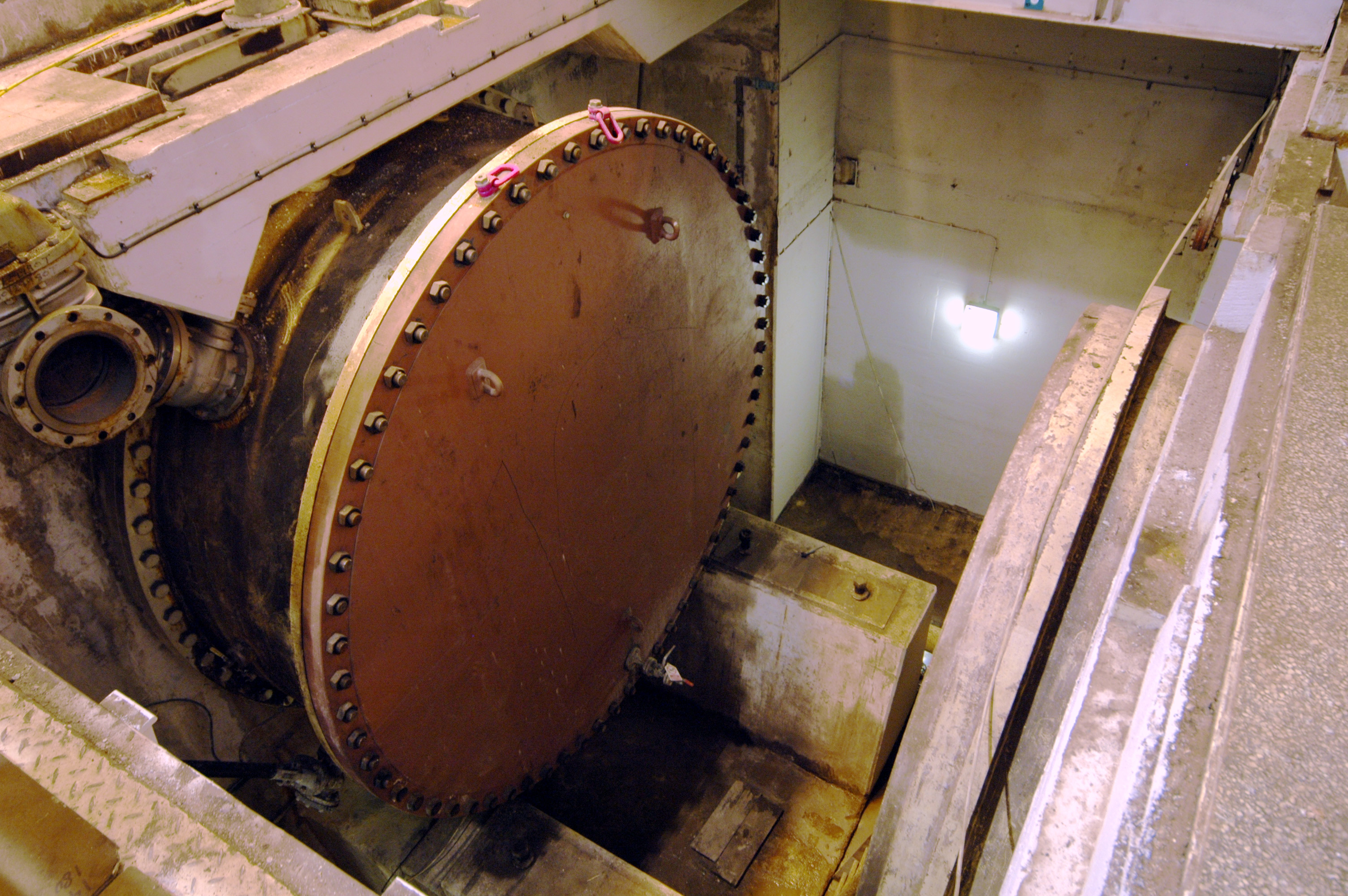 Now looking back to the upstream wall, the outlet of the HP penstock is sealed with a big blank flange - the system was still full of water, running the compensation set. Photo by: Mike Ross 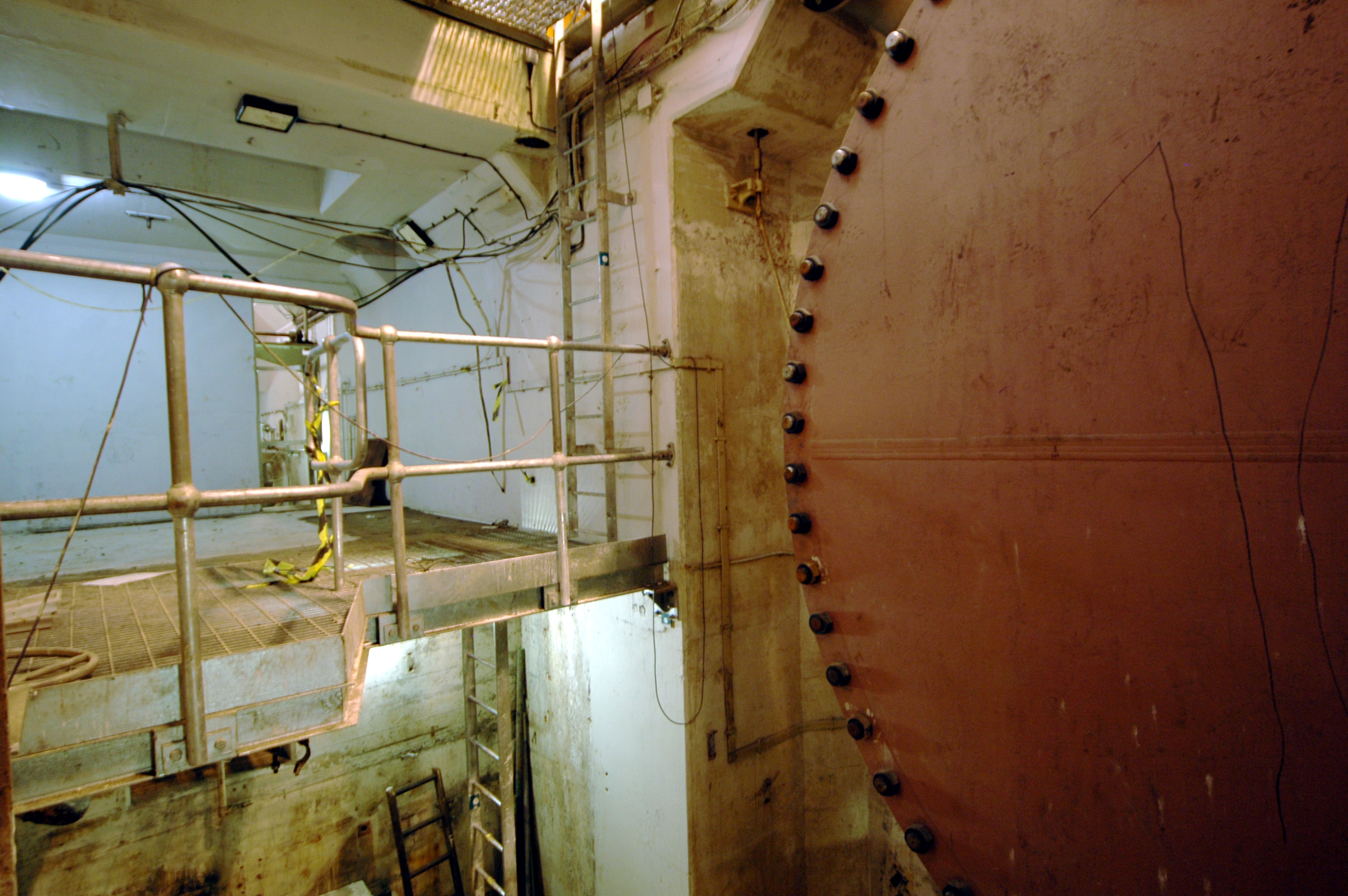 The view from inside the spiral casing - the walkway on the left-hand side shows how the turbine floor level is about the middle of the height of the MIV. Photo by: Mike Ross 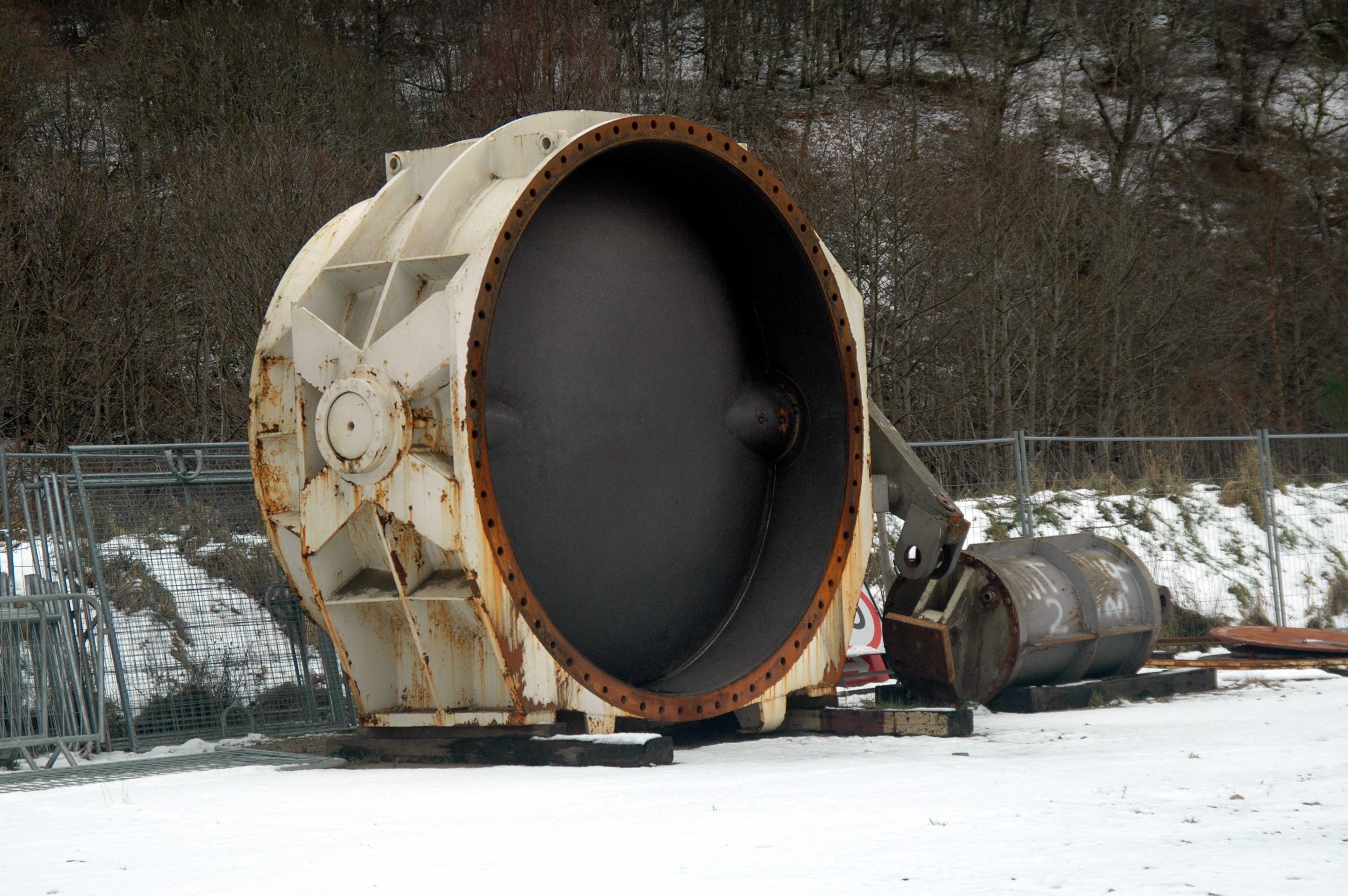 The MIV itself was sat outside, miles away at a compound adjacent to Aigas dam. That's a bloody big valve! Photo by: Mike Ross 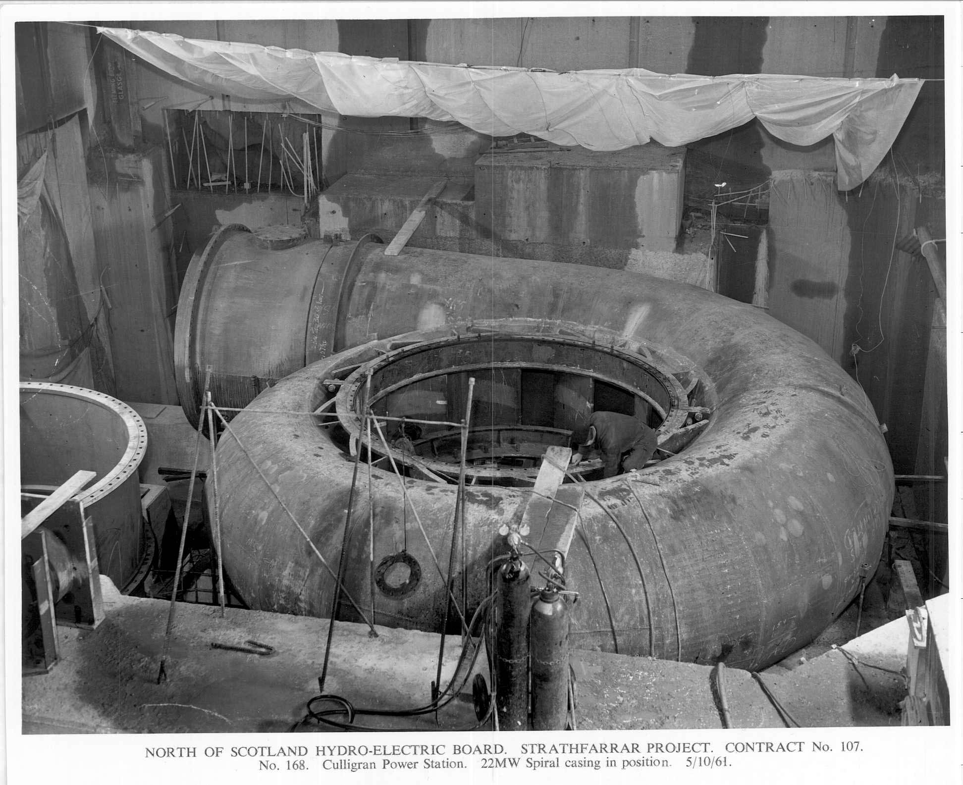 These days the spiral casing is buried in concrete. This archive shot, of the station under erection, shows what the spiral casing looked like before concreting - the MIV goes at the left-hand end of course. Photo by: NOSHEB archives. 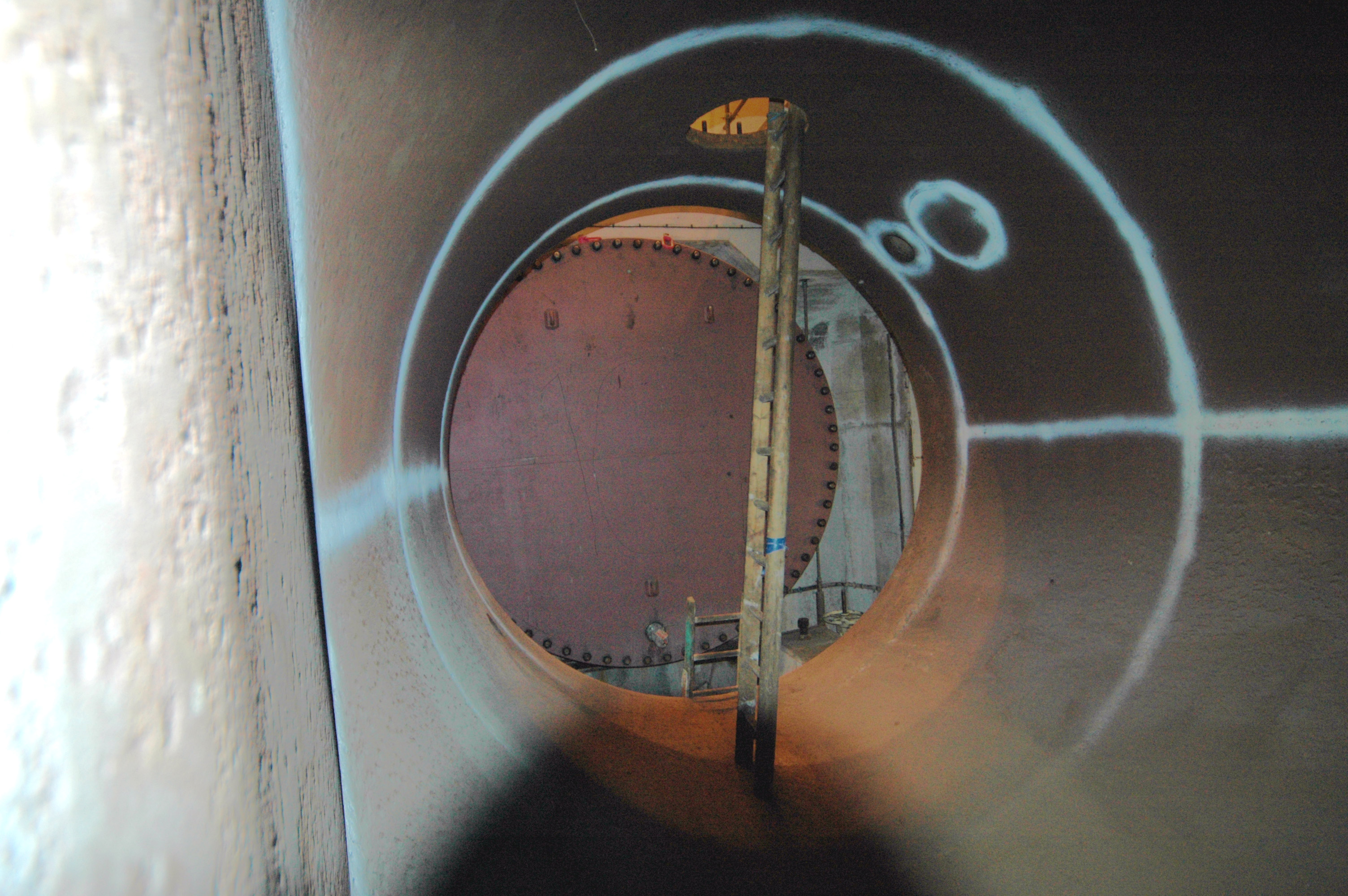 The spiral casing today... compare with pics above; we're inside the spiral, looking back to where the MIV normally sits - note ladder and blank flange. The manhole is the normal means of access to the spiral when the MIV is in place but the system is dewatered.. Photo by: Mike Ross. 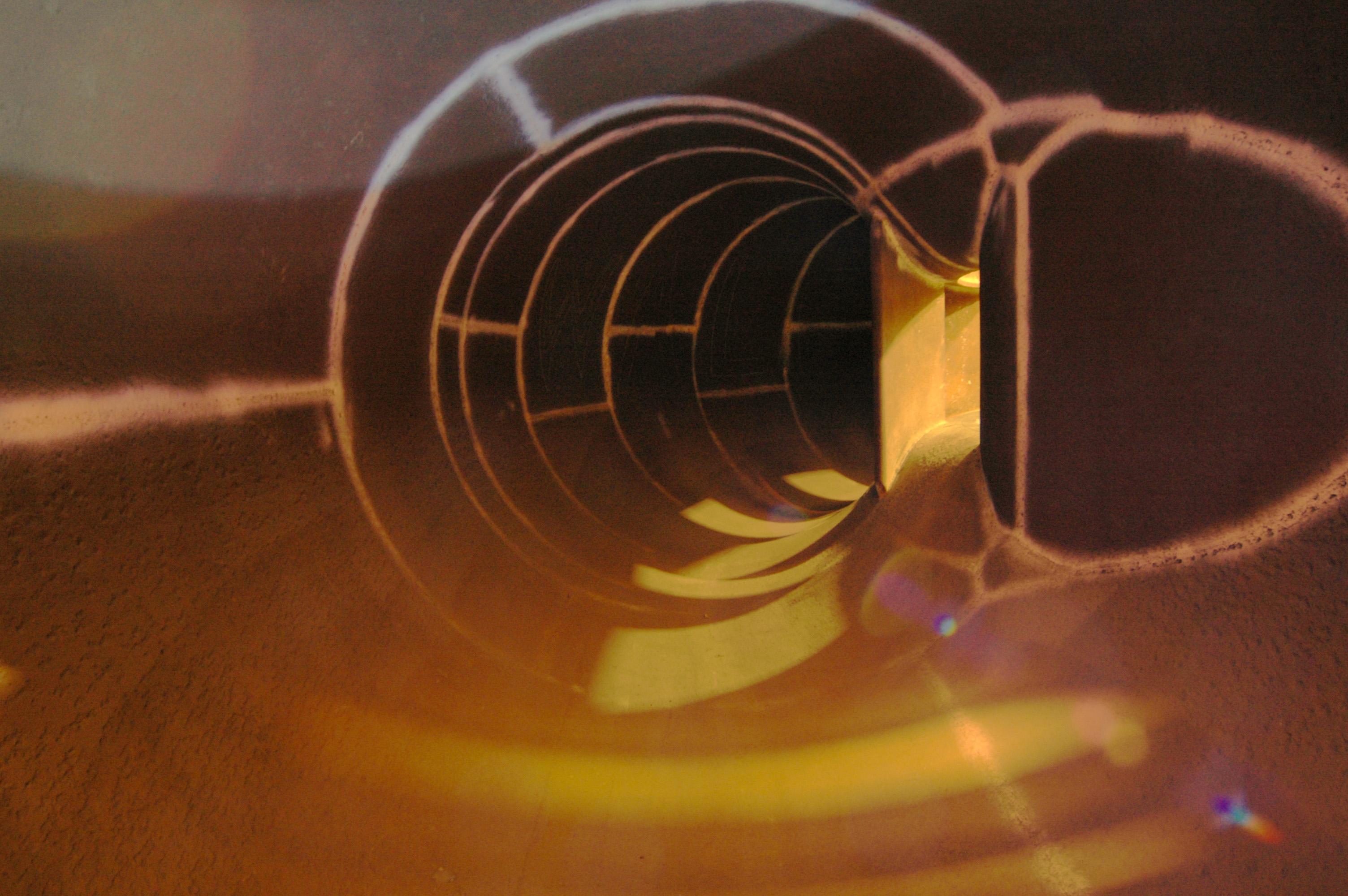 Turning round and looking forward into the spiral - all refurbished, cleaned, painted, welds tested etc. - you can see light from 'outside' shining through the guide vane areas on the right. Photo by: Mike Ross. 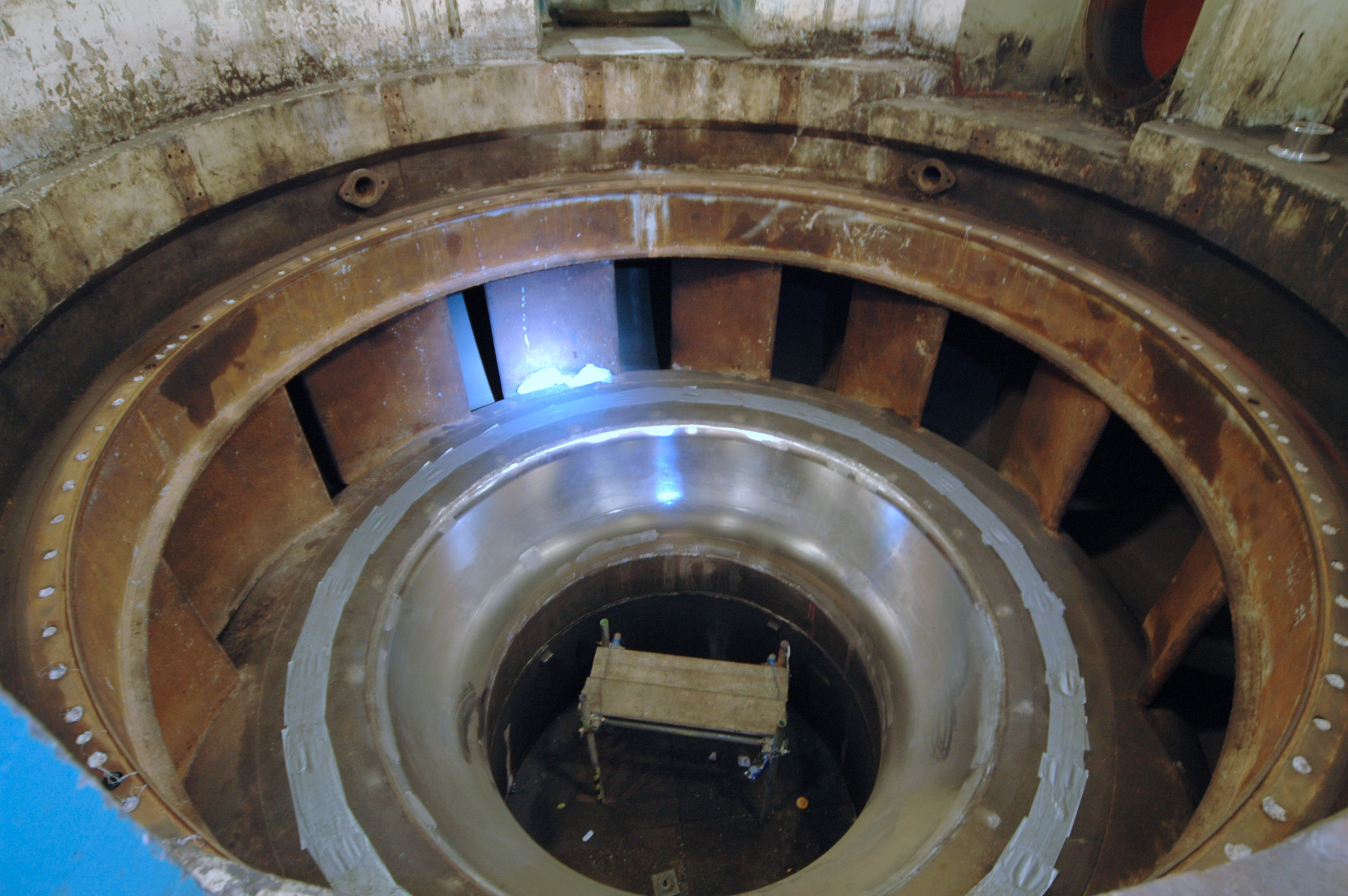 Looking down at the spiral casing from the middle. The water enters from the edge, passes through the guide vanes (guide vane mountings protected by duct tape), then passes through the turbine (turning 90 degrees in the process) which normally sits in the area of burnished metal, before exiting through the draft tube in the middle (filled with scaffolding in the above pic). Photo by: Mike Ross. 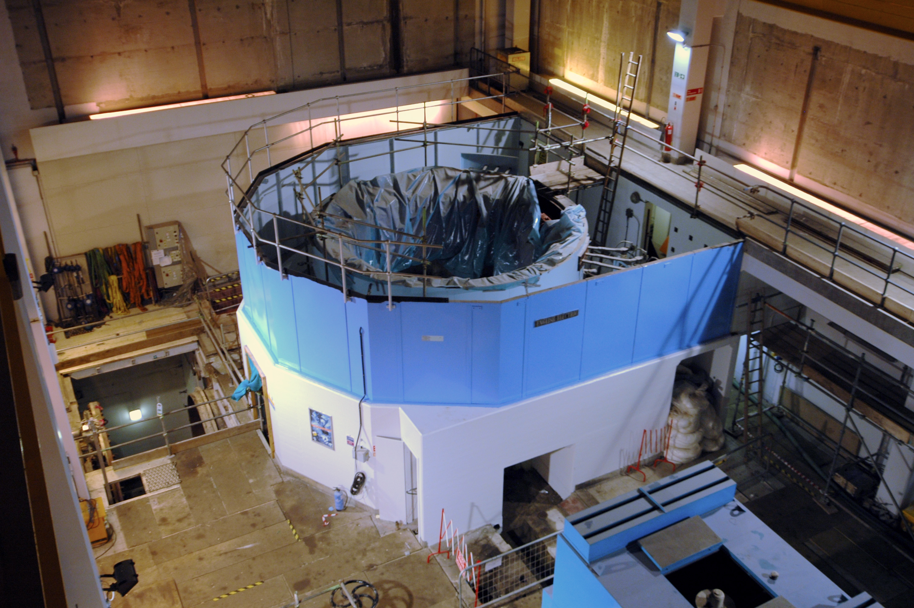 The main turbine was in pieces, the main generator was in pieces too - looking down at the machine from the crane. Photo by: Mike Ross 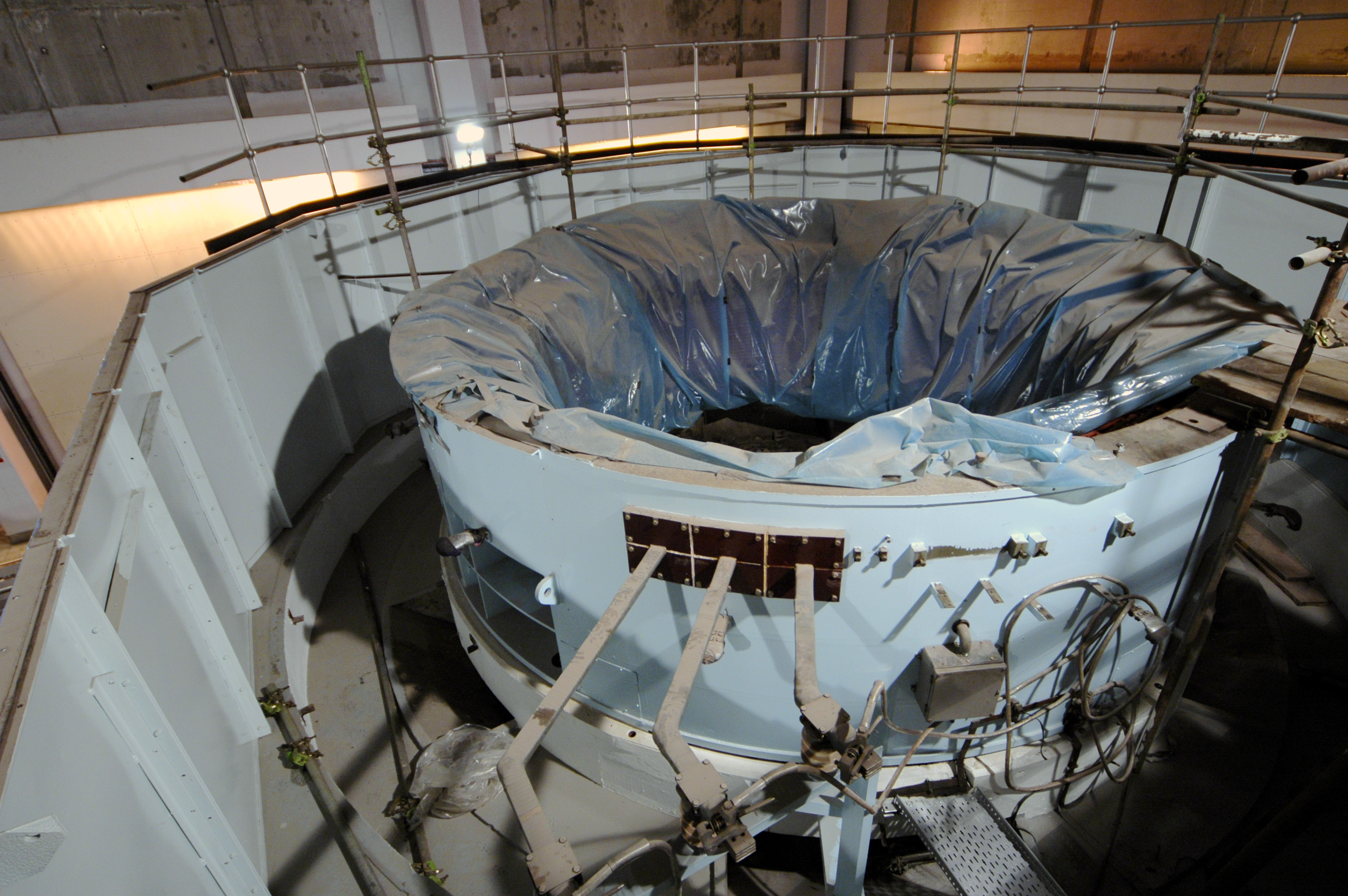 The windings were back in, protected from contamination by sheeting. You can see the busbars which take the current to the cables to the main breaker. Photo by: Mike Ross 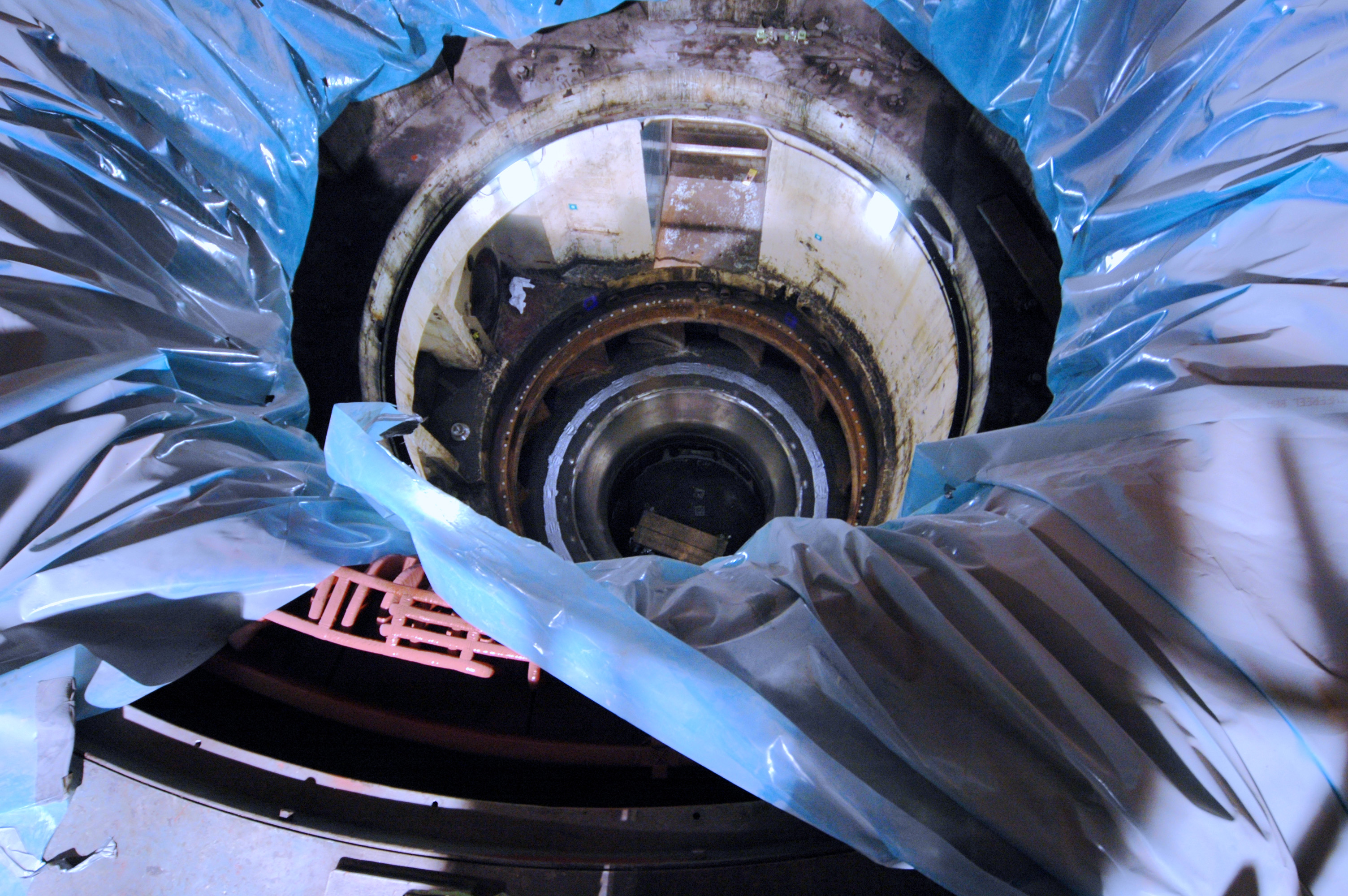 Looking down the whole depth of the machine, between the windings (where the rotor normally sits), through the spiral casing to where the turbine normally sits, and down into the draft tube.. Photo by: Mike Ross Home Page Last updated 13th November 2005 Style © 1998-2001 Subterranea Britannica Words and images © 2005 Michael J. Ross. |