Culligran Power Station - Surge Shaft Since Culligran is fed by a pressure tunnel, an upstream surge shaft is
required to relieve water hammer. It's a differential system, consisting
of two shafts, one of large diameter, one small, with an overflow channel
between them - an almost identical layout to the one used at Deanie. The
drawing on the main Culligran page shows the layout most clearly. 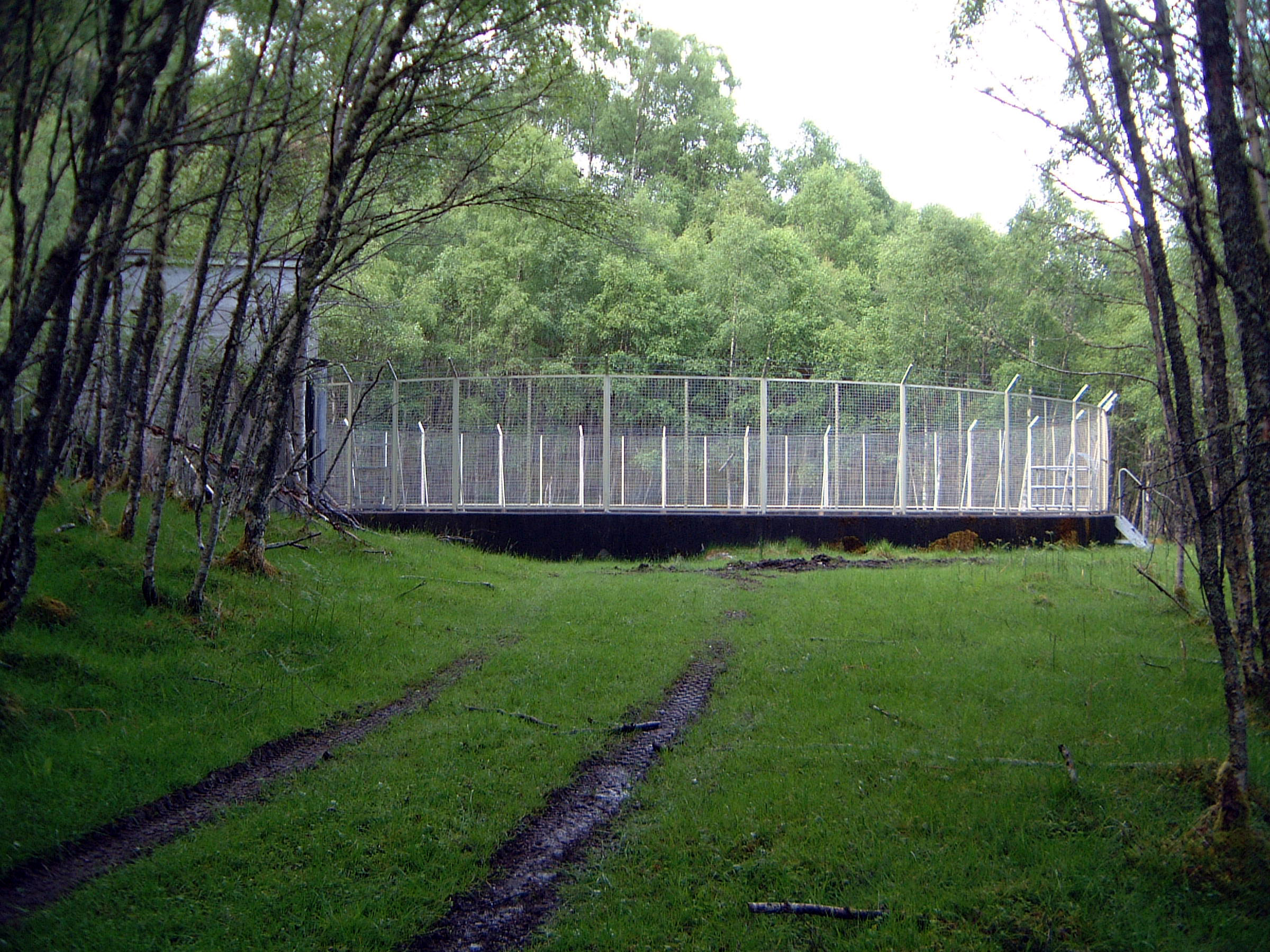 Photo: Culligran surge shaft: approach track Photo by: Mike Ross 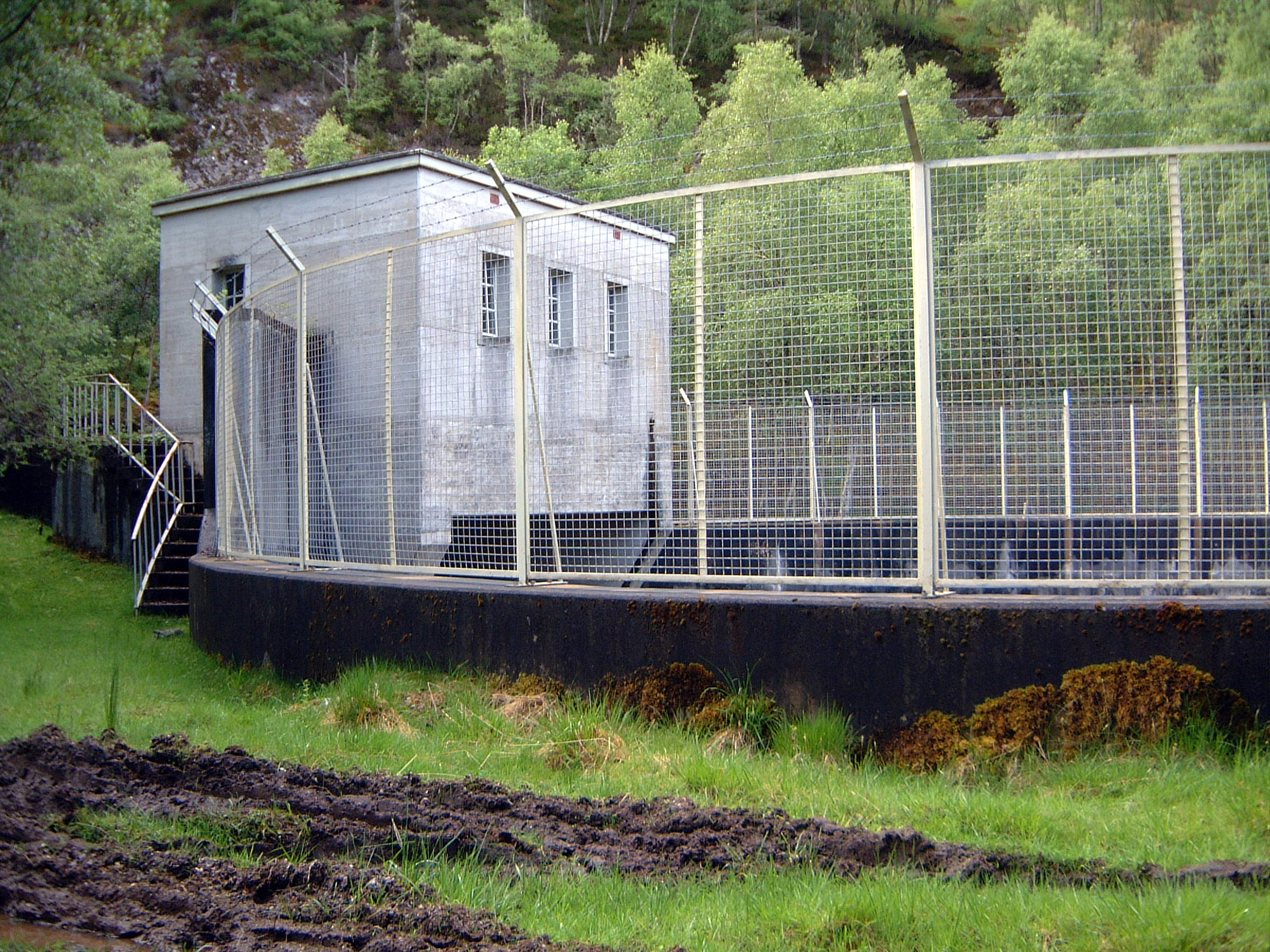 Photo: Culligran surge shaft: gate house Photo by: Mike Ross 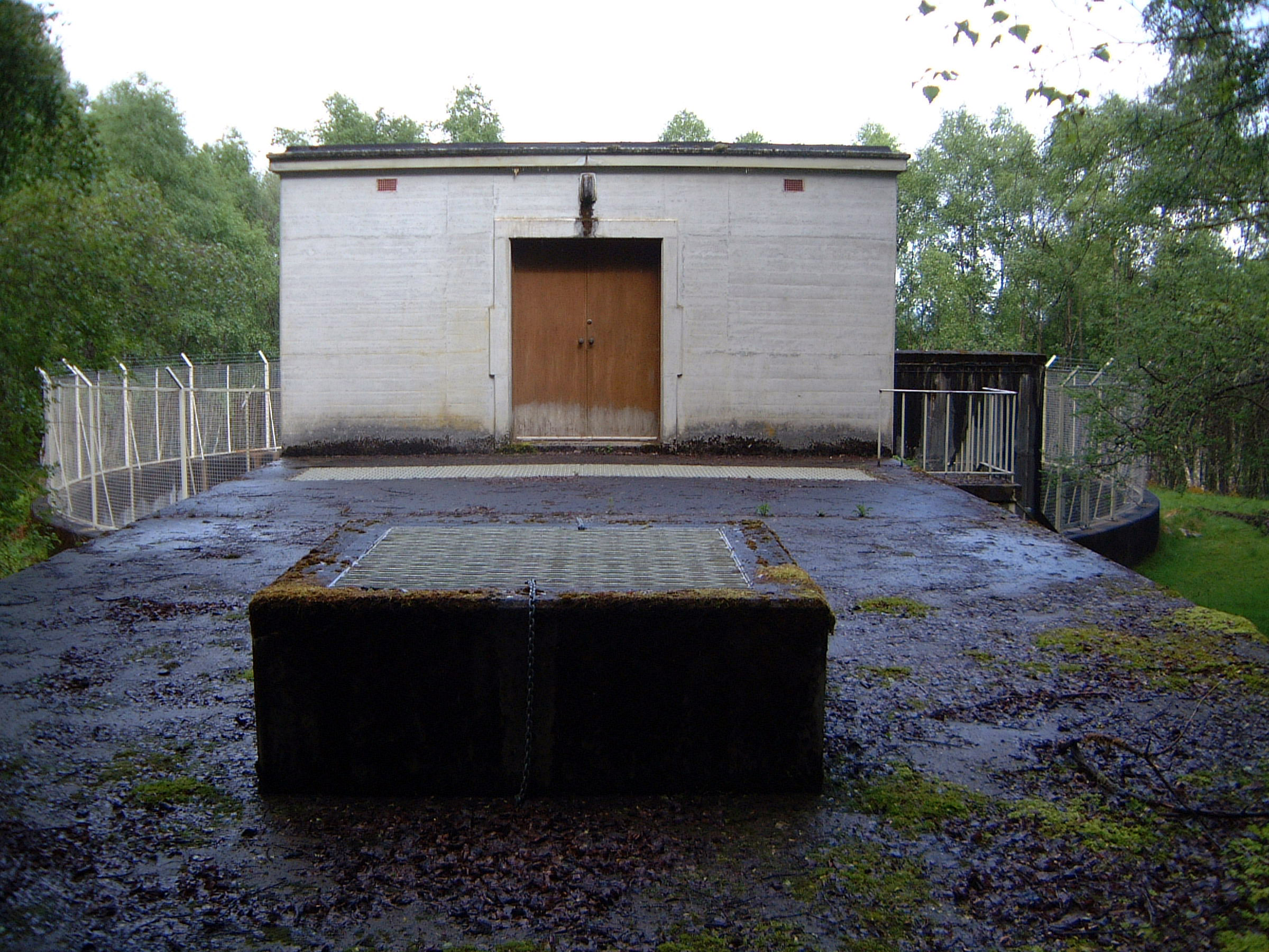 Photo: Culligran surge shaft: gatehouse. from directly over riser shaft ( grille in foreground covers riser). Photo by: Mike Ross 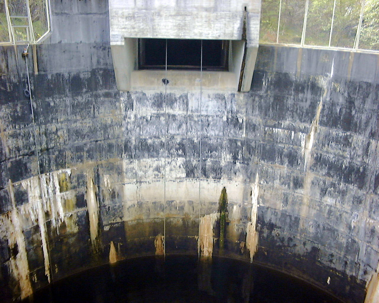 Photo: Culligran surge shaft: looking across main shaft towards gatehouse. Normal water level. Cables for raising/lowering gate can be seen, as can the overflow channel to the riser chamber. Photo by: Mike Ross
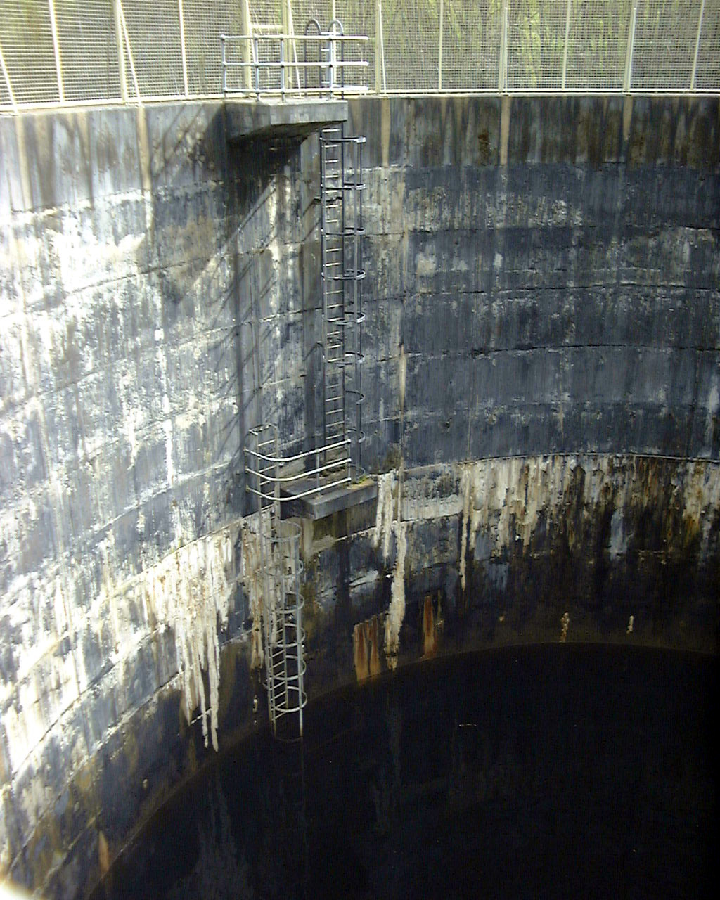
Photo: Culligran surge shaft: main shaft and access ladder. Normal water level. Photo by: Mike Ross Photo: Culligran surge shaft: dewatered. Cables have lowered gate to closed position. Normal water level is obvious. Square structure is 'hood' over orifice to LP tunnel (dark void). Photo by: Mike Ross
Photo: Culligran surge shaft: dewatered. Ladder goes all the way to the floor of the surge shaft. The square object is the bolted cover over the HP shaft. Compare with drawing on main page. Photo by: Mike Ross 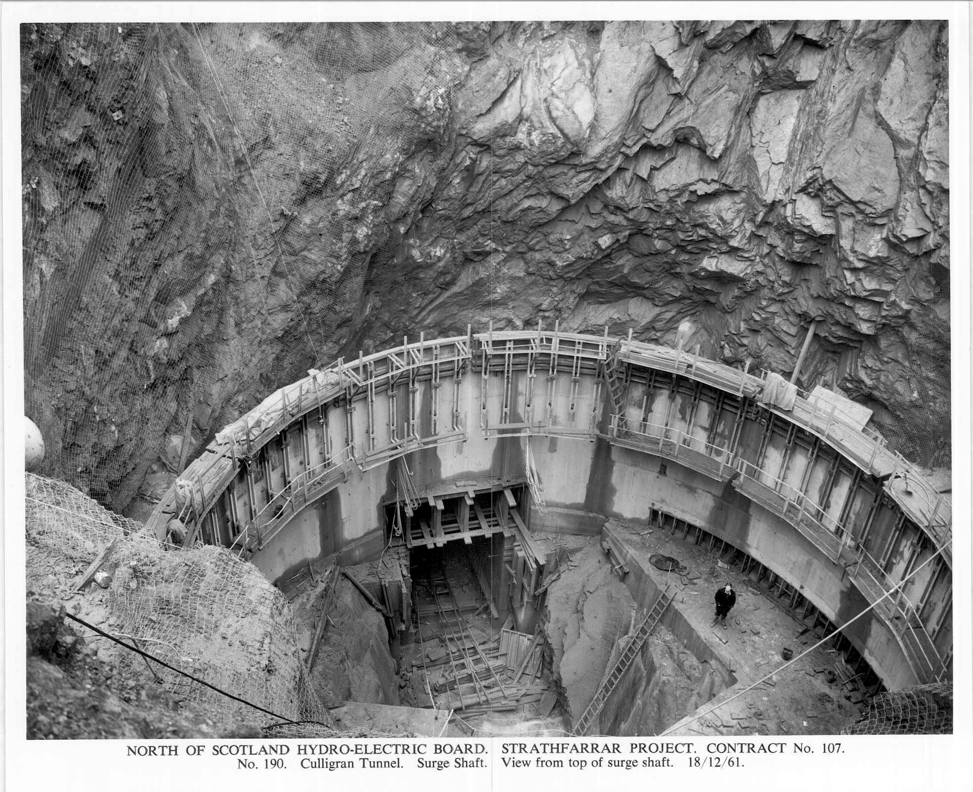 Finally a couple from the archives. Surge shaft fully excavated and lining underway. The obvious tunnel mouth is the outlet of the 17,000ft. LP tunnel from the dam. Photo by: NOSHEB archives  The surge shaft, gatehouse, and riser as completed Photo by: NOSHEB archives. Home Page Last updated 13th November 2005 Style © 1998-2001 Subterranea Britannica Words and images © 2005 Michael J. Ross. |